PCT2075 Temperature Sensor
Contents
PCT2075 Sensor Description
The PCT2075 temperature sensor chip comes from NXP Semiconductors. It's described as a drop-in replacement for the venerable LM75A. And after testing a PCT2075 development board with the micro:bit and a MicroPython LM75A driver this does indeed seem to be the case.
Temperature is measured with a bandgap temperature sensor. This class of sensor relies upon the temperature dependent voltage characteristic of a silicon diode. It is the common technology used in this type of temperature sensor.
The supply voltage for this sensor is 2.7V to 5.5V. Thus it is suitable for both 3.3V and 5V microcontrollers.
The current draw for the PCT2075 during the measurement cycle is approximately 70 µA with the I2 interface idle. This is quite impressive. In Shutdown mode the current draw is <1.0 µA.
Sensor Precision and AccuracyThe PCT2075 produces an 11-bit measurement. This means that it has a resolution of 0.125°C. However if the LM75A equivalent measurement is available if only 9-bits from the Temperature register are used.
The accuracy is better than that for the LM75A and is quoted as:
- ±1°C (-25°C to 100°C)
- ±2°C (-55°C to 125°C)
The PCT2075 is available in several packages; two of which closely match the dimensions of the original LM75A, with a choice of 6 0r 8 leads.
- SO8 : 4.8 mm x 3.8 mm with 8-leads.
- TSSOP : 2.9 mm x 2.9 mm with 8-leads.
- HWSON8 : 2.0 mm x 3.0 mm with 8-leads.
- TSOP : 3.1 mm x 1.7 mm with 6-leads.
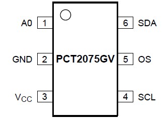
The PCT2075 is available in 8-pin (most common) and 6-pin packages. In the 6-pin version the A1 and A2 addressing pins have been dropped.
The following pinouts are from the product Datasheet.
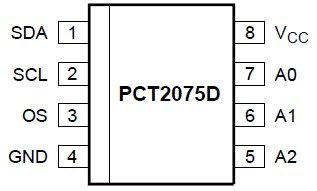
Pin descriptions:
- VCC, GND
Positive power pin and Ground pin respectively.
- SDA, SCL
I2C pins; serial data pin and serial clock pin respectively.
- OS
Over-temperature Shutdown; output pin for the sensor's watchdog function.
- A0, A1, A2
i2C address pins; connected independently to either VCC, GND or left floating to give a choice of 27 different I2C addresses. That means that up to 27 of these sensors can be connected to the same I2C bus!
PCT2075 Registers
The PCT2075 has five registers available to the user; one more than its LM75A predecessor:
| Address | Register | Description |
|---|---|---|
| 0x00 | Temperature | Read-only 16-bit register with the last °C conversion. |
| 0x01 | Configuration | Read/Write 8-bit register configures power and watchdog modes. |
| 0x02 | THYST | Read/Write 16-bit register stores the THYST value. |
| 0x03 | TOS | Read/Write 16-bit register stores the TOS value. |
| 0x04 | TIDLE | Read/Write 8-bit register which controls the temperature conversion cycle time. This is new functionality not available on the the LM75A. |
The watchdog parameters, THYST and TOS, are discussed below.
The required register address is written by the master via the I2C interface. That register can then be written to or read from.
Unlike many other I2C slave devices the register address of the PCT2075 is not auto-incremented. Multiple reads will always read the same register. This is useful in the case of only the temperature being required and the watchdog functions aren't used.
Temperature Measurements
The PCT2075 continually takes temperature measurements. There is no ability for the user to initiate one-shot readings. The datasheets state that a temperature conversion takes about 28ms. After each conversion the sensor will drop back to a low power state till the next measurement/conversion cycle is triggered.
Temperature measurement cycle timesBy default the frequency of temperature conversions is set to 100ms. Thus there is 28ms of temperature ADC conversion followed by 72ms of low-powered wait before the next 100ms cycle commences.
The cycle time is user programmable by writing a value in the 8-bit TIDLE register. The value of this register is multiplied by 100 to give the cycle time in ms. Thus cycle times in increments of 100ms can be configured from 100ms to 3100ms. If only infrequent temperature measurements are needed this feature can be a large power saver.
Reading the temperatureThe temperature data can be requested at any time through the I2C interface.
A single byte (0x00) is written to the sensor. Then two bytes (16-bits) are read. The MSB (most significant byte) contains the integer portion of the temperature reading in °C. It is in two's complement format so that a negative value can be possible.
The LSB (least significant byte) contains the decimal portion. Only Bits[7:5] are used.
These 11-bits (8 + 3) is the temperature in °C represented in two's complement binary format. The Datasheet explains the relatively straight forward process of converting this to the decimal equivalent.
Temperature Watchdog
Many digital temperature-only sensors have a watchdog function. High temperature threshold(s) are set and the watch dog will monitor these upper thresholds against measured temperature and raise an alarm condition if reached or exceeded.
The PCT2075 raises an over-temperature alarm by changing the state of the chip's OS pin. Whether the pin changes from LOW to HIGH or the other way around depends on the OS Polarity bit (Bit[2]) in the Configuration register:
ModesThere are two watchdog modes; with the mode selected by the value of the Cmp/Int bit (Bit[1]) in the Configuration register.
- Comparator Mode
- Interrupt Mode
There are two temperature setpoints, both configurable by the user:
- TOS : This is the over-temperature setpoint that is monitored with an alarm set if reached or exceeded. The user can set (or read) this value by writing (or reading) to the 16-bit TOS register.
- THYST : If an over-temperature alarm has occurred it is considered active till the temperature has cooled to this setting. The user can set (or read) this value by writing (or reading) to the 16-bit THYST register.
If the PCT2075 is being used in a 'noisy' (e.g. industrial) environment to monitor the temperature of some equipment or process there may be false alarms issued. The chip offers some protection against this by allowing a faults queue. The number of consecutive over-temperature faults registered before an over-temperature alarm occurs can be configured.
This can be configured to 1, 2, 4 or 6 faults. The Configuration register Bits[7:5] are used for this purpose.
This is just a very brief summary of the watchdog. You are referred to the product's datasheet for full details.
Power Modes
The PCT2075 has an Active Mode and a Shutdown Mode. The mode is determined by the value of the Shutdown bit (bit[0]) in the Configuration register. Writing a 0 enables Active Mode while writing a 1 forces the sensor into Shutdown Mode.
Shutdown Mode significantly reduces power supply current. No temperature readings are taken so the watchdog is also inactive. The I2C bus is still active, allowing the same read/write access to the sensor's registers as in Active Mode.
PCT2075 MicroPython Driver for micro:bit
A PCT2075 MicroPython driver specifically for the micro:bit has been developed as part of this series on MicroPython for the microbit. The driver webpage also provides a detailed description of the driver's methods with sample code.
The PCT2075 driver is implemented as a derived class with the base class being a driver for the LM75A. This is appropriate as the PCT2075 chip possesses the same functionality but with a couple of enhancements.
The driver is a full implementation of the PCT2075 capabilities as described in the product datasheets.