MicroPython Driver for ADT7410 Sensor
Contents
Introduction
This is a MicroPython driver written specifically for the BBC micro:bit that supports the ADT7410 ambient temperature sensor.
The ADT7410 is a digital temperature only sensor. As well as returning temperature readings it also has a well-featured watchdog which provides under-temperature, over-temperature and critical over-temperature alerting.
The ADT7410 sensor is discussed in some detail here. Its always useful to consult the excellent product datasheet.
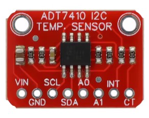
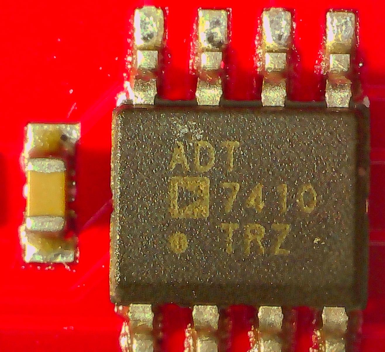
The SSOP packaging of this sensor is not particularly breadboard friendly. Fortunately relatively inexpensive breakout boards are available.
Connecting the ADT7410
The ADT7410 communicates via I2C. Hooking it up to the micro:bit is easy:
| micro:bit | ADT7410 |
|---|---|
| 3.3V | VIN |
| GND | GND |
| Pin 20 | SDA |
| Pin 19 | SCL |
This utilises the standard I2C pins of the micro:bit.
Driver Overview
Problem with ADT7410 boardsWe bought two ADT7410 boards for this driver development project from an online Chinese shop. While testing driver code it became evident that both of these boards suffered from the same major flaw.
It seems that it's possible to reliably write to the chip's registers. However the only value returned when attempting to read any register - with the exception discussed below - was the Temperature register's MSB. A quick online search showed this to be a known issue.
We don't know whether it's an issue with the sensor chip (e.g. a poorly made clone), a design issue with the development board or something else.
Reading the 16-bit word from the Temperature register seemed fine. Writing to the Configuration register also appeared to work as per the datasheet even though the contents of this register couldn't be read back through the I2C interface for conformation.
This driver allows the user to define the data resolution and the sampling mode. This involves writing to the Configuration register. Thorough driver code testing indicated that this appears to work fine.
In view of this inability to read any register except the Temperature register it was decided to concentrate on providing a method for obtaining the temperature. After all, this is the main function of the sensor. Consequently no watchdog functionality is provided in the driver.
Copying the driver code to the micro:bitThe driver code can be:
- Copied from this webpage onto the clipboard then pasted into the MicroPython editor e.g. the Mu Editor. It should be saved as fc_adt7410.py - OR -
- Download as a zip file using the link. Unzip the file and save it as fc_adt7410.py into the default directory where the MicroPython editor e.g. Mu Editor saves python code files.
After saving the fc_adt7410.py file to the computer it should be copied to the small filesystem on the micro:bit. The examples on this page will not work if this step is omitted. Any MicroPython editor that recognises the micro:bit will have an option to do this.
The Mu Editor is recommended for its simplicity. It provides a Files button on the toolbar for just this purpose.
I2C addressThe ADT7410 chip has two pins; A0 and A1 for setting the I2C address. Each pin is connected independently to either VIN or GND. This gives a choice of four addresses.
The breakout board exposes these two pins. Both pins by default are connected to GND which gives an I2C address of 0x48.
Class constructorThe driver is implemented as a class. The first thing to do is call the constructor. This provides an instance of the class.
Syntax:
instance = ADT7410(Addr = 0x48,
                   Resolution = RES_LO,
                   Mode = CONTINUOUS)

Where:
  Addr : The I2C address. It will be in
         the range: 0x48 to 0x4B.

  Resolution : Temperature resolution. One of:
               RES_LO (13-bit) or RES_HI (16-bit)

  Mode : Sampling mode. One of:
         CONTINUOUS, ONE_SHOT, ONE_SPS
  These three modes with code examples are
  discussed below.

Example:
from fc_adt7410 import *

# Declare a sensor with default arguments:
# I2C address = 0x48
# Resolution = RES_LO
# Mode = CONTINUOUS
my_sensor1 = ADT7410()

# Declare a sensor with a different address
my_sensor2 = ADT7410(0x49)
This assumes that the file fc_adt7410.py has been successfully copied to the micro:bit's filesystem as described above.
Methods and FunctionsThe driver provides the following public methods:
- Read()
- ShutDown()
- WakeUp()
The function CtoF() is also available to convert °C to °F.
Using the Driver's Methods
Syntax:
Read()

Purpose:
  Returns the most recent temperature reading in °C.

Example:
from fc_adt7410 import *
# Declare a sensor with default arguments:
my_sensor1 = ADT7410()
# Read the temperature
T = my_sensor1.Read()
# Output the temperature
print('Temperature is:', T, 'C')

Output:
Temperature is: 19.75 C
Syntax:
CtoF(C, d)

Purpose:
  Converts a temperature in degrees Centigrade to degrees Fahrenheit.

Where:
  C : Temperature in degrees Centigrade
  d : Rounded to this number of decimals (default = 1)

Example:
from fc_adt7410 import *
C = 22.46
F = CtoF(C, 2)
print(C, 'C =', F, 'F')

Output:
22.46 C = 72.43 F
Syntax:
ShutDown()

Purpose:
  Puts the sensor in deep sleep. The internal circuits
  are powered down. Only the I2C interface is active.
  The last temperature conversion before deep sleep
  can still be read. No more temperature updates are
  performed while in this state.

Syntax:
WakeUp()

Purpose:
  Wakes up the sensor after deep sleep. The pre-sleep
  configuration is written to the Configuration register.
  Temperature conversions recommence.

Example:
from fc_adt7410 import *
from microbit import sleep

sensor = ADT7410()
# Shutdown the sensor for 5 seconds.
sensor.ShutDown()
sleep(5000)
# Wake the sensor and read the temperature.
sensor.WakeUp()
print('Temperature:', sensor.Read())

Output:
Temperature: 21.625
Temperature Sampling Modes
The ADT7410 temperature sensor has three different temperature sampling modes. The different modes offer the user the choice of frequent temperature updates or slower update rates with the advantage of considerable power savings.
Continuous
This is default sampling mode when the sensor chip powered-up or soft reset. In the product datasheet it is also referred to as the Normal mode.
A temperature conversion takes 240 ms to complete and the ADT7410 is continuously converting. The latest temperature value can be read at any time through the I2C interface.
Example:
# Test 'Continuous' mode on the
# ADT7410 temperature sensor.

from fc_adt7410 import *

# Set up sensor for 16-bit resolution
# and Continuous mode sampling.
sensor = ADT7410(Resolution=RES_HI, Mode=CONTINUOUS)
print('Resolution is 16 bits')
print("Mode is 'Continuous'")
print('Interval between samples is 600ms\n')

for _ in range(0, 5):
    T = sensor.Read()
    print(T, 'C')
    sleep(600)
print()
Output:
Resolution is 16 bits
Mode is 'Continuous'
Interval between samples is 600ms

24.80469 C
24.79687 C
24.79687 C
24.82031 C
24.75781 C
1 SPS
This mode takes one sample per second on a continuous basis. Each temperature conversion only takes 60 ms to complete. The ADT7410 chip then waits the remainder of the one second period (940 ms) before initiating the next conversion.
Example:
# Test '1 Sample per Second' mode
# on the ADT7410 temperature sensor.

from fc_adt7410 import *

sensor1 = ADT7410(Resolution = RES_HI, Mode = ONE_SPS)
print('Resolution is 16 bits')
print("Mode is '1 Sample per Second'")
print('Interval between samples is 600ms\n')

for s in range(0, 7):
    T = sensor1.Read()
    print('Sample#', s+1, ', Temperature:', T, 'C')
    sleep(600)
print()
Output:
Resolution is 16 bits
Mode is '1 Sample per Second'
Interval between samples is 600ms

Sample# 1 , Temperature: 25.73437 C
Sample# 2 , Temperature: 25.73437 C
Sample# 3 , Temperature: 25.75 C
Sample# 4 , Temperature: 25.75 C
Sample# 5 , Temperature: 25.77344 C
Sample# 6 , Temperature: 25.80469 C
Sample# 7 , Temperature: 25.80469 C
In the example above, a temperature reading is being requested every 600 ms. Since a new temperature value is being produced only once per second some of the temperatures will be stale.
Looking at the output, this is indeed the case. Sample# 2, Sample# 4 and Sample# 7 are all stale values.
One-Shot
In this mode, as the name suggests, the ADT7410 completes a temperature conversation then immediately goes into shutdown. This mode is useful if there is a need to minimise power consumption.
The only part of the chip still active during shutdown is the I2C interface. The last temperature conversion before shutdown mode was activated can still be read at any time.
The chip's Configuration register is written to wake it up and place it back into One-Shot mode when the next temperature conversion is required. It takes about 240 ms before the next temperature reading is available.
This MicroPython driver performs the wake up and restores the previous configuration each time the user calls the Read() method.
Example:
# Test 'One Shot' mode
# on the ADT7410 temperature sensor.

from fc_adt7410 import *

sensor1 = ADT7410(Resolution=RES_HI, Mode=ONE_SHOT)
print('Resolution is 16 bits')
print("Mode is 'One Shot'")
print('Interval between samples is 2 sec\n')

# On each request for another temperature reading
# the Read() method will wake up the ADT7410 chip
# and wait for the next temperature reading to
# become available before returning it.
for _ in range(0, 5):
    T = sensor1.Read()
    print(T,'C ', CtoF(T,2), 'F')
    sleep(2000)
print()
Output:
Resolution is 16 bits
Mode is 'One Shot'
Interval between samples is 2 sec

26.30469 C  79.35 F
26.28906 C  79.32 F
26.3125 C  79.36 F
26.25781 C  79.26 F
26.30469 C  79.35 F
Handling I2C Exceptions
The ADT7410 driver code does not handle any exceptions raised. This is left to the user's program. The example below demonstrates how this can be done.
Example:
# Demonstrate code that handles an exception
# if it occurs during sensor configuration
# in the constructor.

from fc_adt7410 import *

# Set up sensor with defaults.

try:
    sensor1 = ADT7410()
except:
    print('Initialisation of the sensor was NOT successful\n')
else:
    print('Initialisation of the sensor was successful\n')
    print('Resolution is 13 bits')
    print("Mode is 'Continuous'")
    print('Interval between samples is 600ms\n')

    for _ in range(0, 5):
        T = sensor1.Read()
        print(T, 'C')
        sleep(600)
    print()
finally:
    print('Program ending')
Output:

Initialisation of the sensor was successful

Resolution is 13 bits
Mode is 'Continuous'
Interval between samples is 600ms

25.625 C
25.6875 C
25.6875 C
25.625 C
25.625 C

Program ending
ADT7410 Driver Code for micro:bit
Download as zip file
'''
ADT7410 temperature sensor
MicroPython driver for BBC micro:bit

This driver concentrates on returning
temperature measurements.
No watchdog functions are provided.

REFERENCES:
ADT7410 Datasheet
https://www.fredscave.com/drivers/024-adt7410.html

AUTHOR: fredscave.com
DATE  : 2025/04
VERSION : 1.00
'''

from microbit import i2c, sleep
from micropython import const

I2C_ADDR    = const(0x48)
CMD_RESET   = const(0x2F)

# Registers
REG_TEMP    = const(0x00)
REG_CONFIG  = const(0x03)

# Modes
CONTINUOUS    = const(0x00)
ONE_SHOT      = const(0x20)
ONE_SPS       = const(0x40)
SHUT_DOWN     = const(0x60)

# Resolution
RES_HI = const(0x80)
RES_LO = const(0x00)

# Centigrade to Fahrenheit
CtoF = lambda C, d=1: round((C * 9/5) +32, d)

class ADT7410():
    # Constructor sets up I2C address, resolution and mode.
    def __init__(self, Addr = I2C_ADDR,
                 Resolution = RES_LO, Mode = CONTINUOUS):
        self.buf = bytearray(2)
        self.Addr = Addr
        self._Reset()
        if Resolution == RES_HI:
            self.Resolution = RES_HI
        else:
            self.Resolution = RES_LO
        if Mode not in (CONTINUOUS, ONE_SHOT, ONE_SPS):
            self.Mode = CONTINUOUS
        else:
            self.Mode = Mode
        self._SetMode()
        self.UserShutdown = False

    # User method to call to return latest temperature.
    # Resolution and sampling mode are as set by the
    # constructor.
    def Read(self):
        if self.Mode == ONE_SHOT and not self.UserShutdown:
            self.WakeUp()
        i2c.write(self.Addr, bytes([REG_TEMP]))
        self.buf = i2c.read(self.Addr, 2)
        return self._Temperature()

    # Forces the sensor into shutdown mode.
    # All chip internals are switched off.
    # The I2C interface is still active.
    # The last temperature conversion is still available.
    def ShutDown(self):
        i2c.write(self.Addr, bytes([REG_CONFIG, SHUT_DOWN]))
        self.UserShutdown = True

    # Wake upt he sensor from shutdown mode.
    # Temperature conversions commence based on
    # the mode and resolution set by the constructor.
    def WakeUp(self):
        self._SetMode()
        self.UserShutdown = False

    # Soft reset of the chip. All default values
    # are loaded which override any settings that
    # that may have been made in the constructor.
    def _Reset(self):
        i2c.write(I2C_ADDR, bytes([CMD_RESET]))
        sleep(300)

    # Writes a byte to the Configuration register
    # to set the resolution and mode as passed to
    # the constructor.
    def _SetMode(self):
        Config = self.Mode
        if self.Resolution == RES_HI:
            Config = Config | RES_HI
        i2c.write(self.Addr, bytes([REG_CONFIG, Config]))
        sleep(250)

    # Converts the 13-bit or 16-bit two's complement
    # binary value to the decimal equivalent.
    def _Temperature(self):
        positive = (self.buf[0] >> 7) == 0
        if self.Resolution == RES_LO:
            raw = self.buf[0]*256 + self.buf[1] >> 3
            if positive:
               return raw/16
            else:
               return (raw - 8192) / 16
        else:
            raw = self.buf[0]*256 + self.buf[1]
            if positive:
                return raw/128
            else:
                return (raw - 65536) / 128
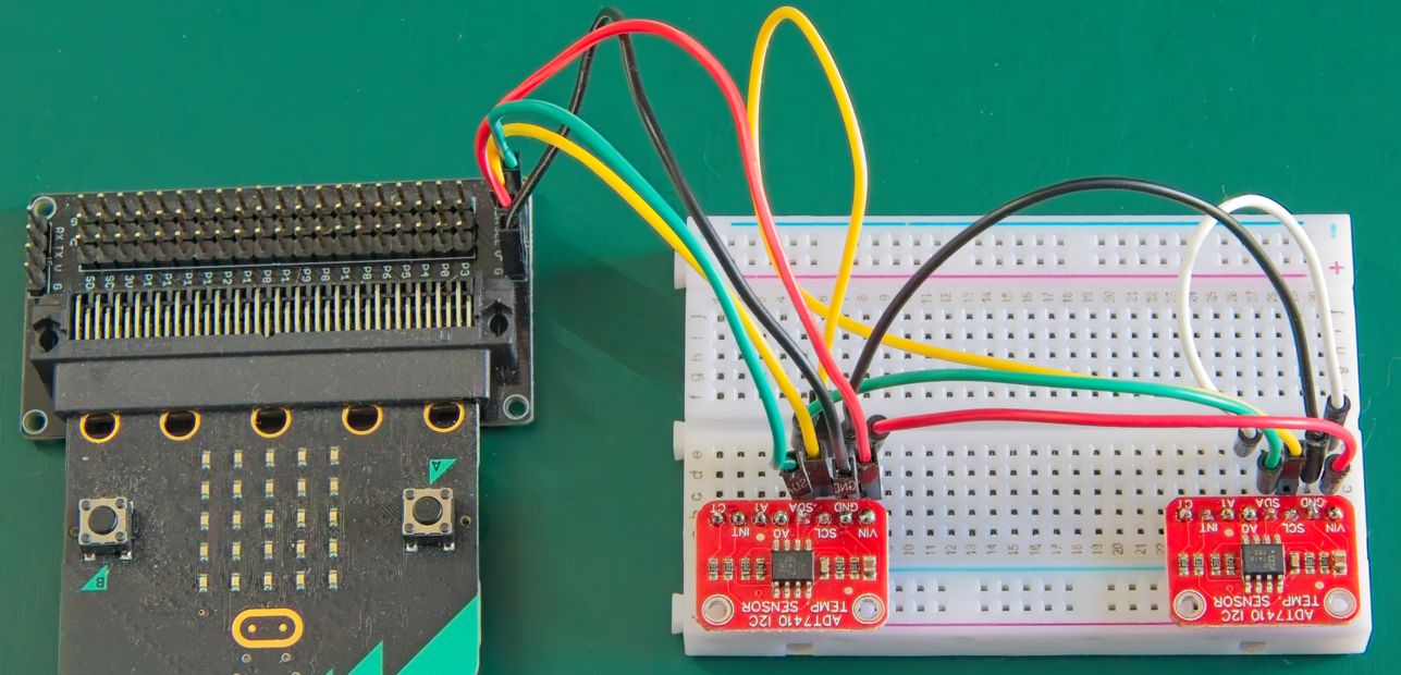
Using Multiple ADT7410 Sensors
A maximum of 4 x ADT7410 sensors can share the same I2C bus. This is possible by tying the A0 and A1 pins in different combinations to VIN and GND.
This example shows just how easy to do this. Two ADT7410 breakout boards are connected to the micro:bit's I2C bus and temperatures are read simultaneously from both sensors.
Hooking up the sensors
- Connect VIN of each sensor to micro:bit's 3.3V pin.
- Connect GND of each sensor to micro:bit's GND pin.
- Connect SCL pin of each sensor to micro:bit's pin19.
- Connect SDA pin of each sensor to micro:bit's pin20.
- On one (only) of the sensors, connect a jumper between A0 and GND. This will change the default I2C address to 0x49.
- Ensure that the driver file fc_adt7410.py has been copied to the micro:bit's filesystem.
The Code:
# Test 2 x ADT7410 temperature sensors.
# Sensor1 has the default I2C address of 0x48.

# Sensor2 has jumper between A0 and VIN pins.
# This changes the I2c Address to 0x49.

from fc_adt7410 import *

# Create the two sensor objects.
adt7410_1 = ADT7410()
adt7410_2 = ADT7410(Addr=0x49)

# Print out the configuration of the sensors.
print('Configuration for both sensors:')
print('Resolution is 13-bits')
print("Mode is 'Continuous'")
print('Interval between samples is 5 seconds\n')

# Take six readings simultaneously from each of
# the sensors with a sample interval of 5 sec.
# Output the results, rounded to two decimals.
for _ in range(0, 6):
    T1 = adt7410_1.Read()
    T2 = adt7410_2.Read()
    print('T1=', round(T1, 2),
          '     T2=', round(T2, 2))
    sleep(5000)
print()
Example Output:
Configuration for both sensors:
Resolution is 13-bits
Mode is 'Continuous'
Interval between samples is 5 seconds

T1= 25.19      T2= 24.69
T1= 25.19      T2= 24.69
T1= 25.25      T2= 24.69
T1= 25.25      T2= 24.75
T1= 25.25      T2= 24.75
T1= 25.25      T2= 24.69
Wrapping Up
As can be seen from the output that was obtained during the development of this example, the two sensors produced temperature readings that matched fairly closely.
Enjoy!